
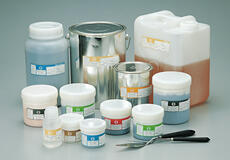
Silver Adhesive Pastes for Die-bonding
What is "Silver Adhesive Pastes for Die-Bonding"?
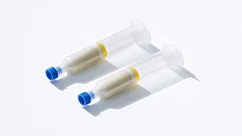
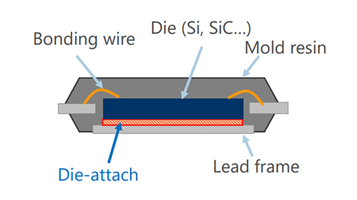
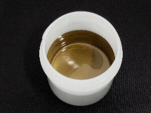
Die-bonding refers to the process and materials used to attach semiconductor chips to substrates. Silver adhesive pastes are used for this bonding, exhibiting high thermal conductivity and reliability. They are used in fields such as next-generation power semiconductors and electric vehicles, where high heat resistance and performance are required. TANAKA offers a lineup of products that combine metal sintering and resin bonding using its proprietary hybrid technology to achieve stress relaxation and high bonding reliability.
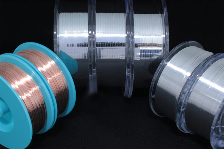
Ag Adhesive Pastes with High Thermal Conductivity and High Reliability
Conductive adhesives for die bonding are used with Si for power devices and SiC and GaN next-generation semiconductors.
Our lineup includes hybrid types that allow a balance of high thermal conductivity and high reliability and sintering types with high thermal conductivity exceeding 200W/m・K.
Overview of Silver Adhesives for Die bonding
Features
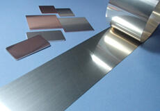
- High thermal conductivity silver adhesive paste lineup for various applications
- Highly reliable, proven products for automotive applications
- Alternative to high-temperature Pb solder pastes
Main product lineup
| Product name | Type | Volume resistivity (µΩ・cm) |
Thermal conductivity (W/m・K) |
Features | Applications |
|---|---|---|---|---|---|
| TS-985シリーズ | Hybrid* Sintering |
7 | 130-240 | High thermal conductivity Alternative to solder High reliability |
Automotive Power IC Power Module |
| TS-987シリーズ | Hybrid | 5 | 160 | High thermal conductivity Alternative to AuSn solder |
LED Laser diode High-frequency module |
| TS-185シリーズ | Epoxy | 10 | 80 | High thermal conductivity High reliability |
Automotive Power IC LED Laser diode |
| TS-333シリーズ | Thermoplastic | 25 | 23 | High thermal conductivity Low stress |
Automotive Power IC |
| TS-175シリーズ | Epoxy | 32 | 13 | High thermal conductivity Low stress |
Power IC RF Module Laser diode |
| TS-160シリーズ | Epoxy | 200 | 2.5 | High reliability | LED Laser diode Others |
*Hybrid = Sintering + Resin Bonding
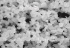
TANAKA Original Hybrid Sintering
Conceptual Images of Bonding
TS-160, 175 series, TS-185, 333 series
TS-985 series, TS-987 series
= Hybrid sintering
TS-985 Series
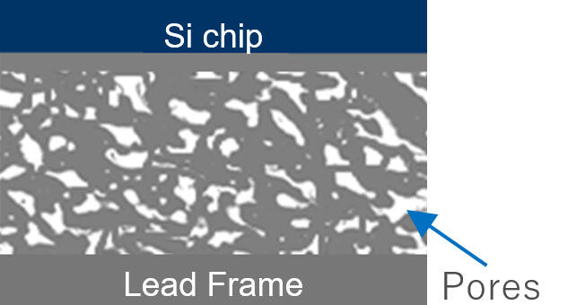
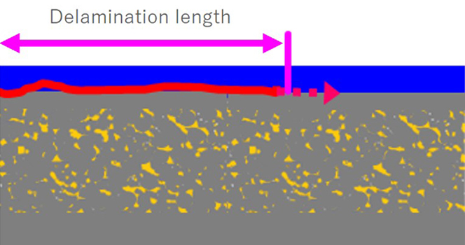
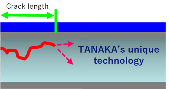
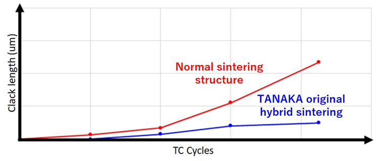
Reliability and Characteristics of Hybrid Sintering
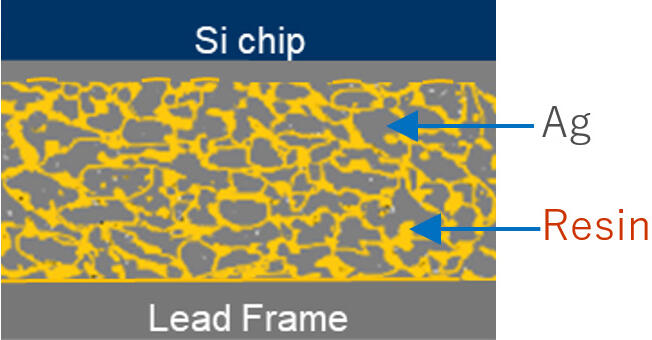
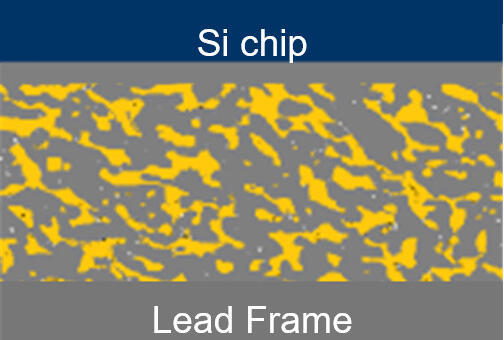
Normal (hybrid) sintering structure
TANAKA original hybrid sintering
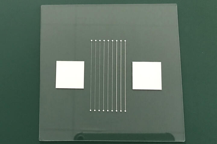
7x7mm Au sputtered chip/ Bare-CuLF (without mold resin)
Clack / delami length
Related Information

Please Inquiry
Please feel free Inquiry with any inquiries regarding products, media, competitive funding, etc.